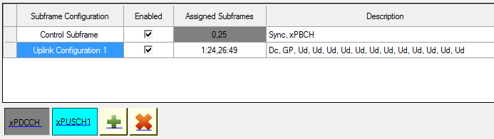
Uplink Configuration
There are total 5 uplink configurations. The associated channels and subframe layout with each uplink configuration are as below. User can add or remove multiple Xpusch to have multi-transmission. When resource allocation conflict occurs between channels, the channel block with conflict will display an icon on the right-top of the button and user needs to resolve it before generating the waveform.
xPDCCH
The xPUCCH is available in Downlink configuration 2/4 and Uplink configuration 2/5, and it can only be transmitted in the last symbol of a subframe. For downlink configuration, xPUCCH is off by default.
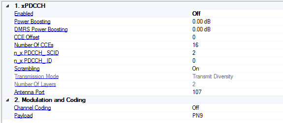
1. xPDCCH
Enabled
Select/ deselect the Enable check box to enable/ disable the channel or signal in a radio frame.
Power Boosting
Range: -40 - 40
Default: 0
Set the additional power boosting for the channel.
DMRS Power Boosting
Range: -40 - 40
Default: 0
Set the DMRS power relative to data part.
CCE Offset
Range: 0 - 14
Default: 0
Set the CCE offset indicating where xPDCCH starts from. It's only configurable when channel coding is Off.
Number Of CCEs
Range: 2 - 16
Default: 16
Set the number of CCEs allocated to xPDCCH. It's only configurable when channel coding is Off.
n_xPDCCH_SCID
Range: 0 - 65535
Default: 2
Set the n_xPDCCH_SCID for DMRS sequence generation.
n_xPDCCH_ID
Range: 0 - 65535
Default: 0
Set the n_xPDCCH_ID for DMRS sequence generation.
Scrambling
Enable or disable the scrambling for the channel.Transmission Mode
.Choices: Single Antenna Port | Transmission Diversity | Spatial MultiplexingDefault: Single Antenna PortSelect the channel transmission mode that determines the layer number and available antenna ports.
Number of Layers
Range: 1 - 2
Default: 1
Set the number of layers for the selected transmission mode. It's only configrable in spatial multiplexing mode.
Antenna Port
Set the antenna port on which the symbols will be generated into the waveform.
2. Modulation and Coding
Channel Coding
Enable or disable transport layer channel coding. When disabled, raw payload data will be passed to scrambler directly.
When channel coding is on, user can bring up the DCI transmission configuration form to view or configure.

DCI Transmissions
Click the  button to bring up the
  DCI Transmission dialog.
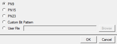
Payload
Choices: PN9 | PN15 | PN23 | Custom Bit Pattern | User File
Default: PN9
Bring up the Payload Editor to select the data bits used for the channel payload.
xPUSCH
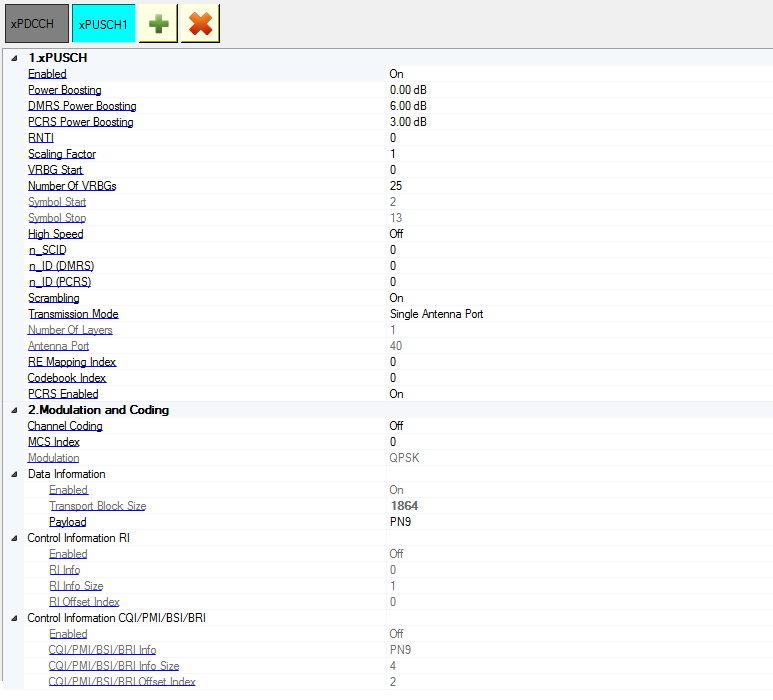
1. xPUSCH
Enabled
Select/ deselect the Enable check box to enable/ disable the channel or signal in a radio frame.
Power Boosting
Range: -40 - 40
Default: 0
Set the additional power boosting for the channel.
DMRS Power Boosting
Range: -40 - 40
Default: 0
Set the DMRS power relative to data part.
PCRS Power Boosting
Range: -40 - 40
Default: 0
Set the PCRS power relative to data part.
RNTI
Range: 0 - 65535
Default: 0
Set the RNTI for the channel.
Scaling Factor
Range: 0 - 10
Default: 1
Set the scaling factor to adjust the channel power.
VRBG Start
Range: 0 - 24
Default: 0
Set the start index of VRBG assigned to the channel. When a resource allocation conflict occurs, the channel block color will become red. User needs to resolve this conflict before generating the signal.
Number Of VRBGs
Range: 1 - 25
Default: 25
Set the number of VRBGs assigned to the channel. It will be automatically updated when VRBG Start + Number exceeds the max VRBG number of 25. When a resource allocation conflict occurs, the channel block color will become red. User needs to resolve this conflict before generating the signal.
Symbol Start
Display the start index of OFDM symbols assigned to the channel. It's determined by the subframe configuration.
Symbol Stop
Display the index of last OFDM symbol assigned to the channel. It's determined by the subframe configuration.
High Speed
Enable or disable high speed case, which will add an addition DMRS at symbol 10.
n_SCID
Range: 0 - 65535
Default: 0
Set the n_SCID for DMRS sequence generation.
n_ID (DRMS)
Range: 0 - 65535
Default: 0
Set the n_ID for DMRS sequence generation.
n_ID (PCRS)
Range: 0 - 65535
Default: 0
Set the n_ID for PCRS sequence generation.
Scrambling
Enable or disable the scrambling for the channel.
Transmission Mode
Choices: Single Antenna Port | Transmission Diversity | Spatial Multiplexing
Default: Single Antenna Port
Select the channel transmission mode that determines the layer number and available antenna ports.
Number of Layers
Range: 1 - 2
Default: 1
Set the number of layers for the selected transmission mode. It's only configrable in spatial multiplexing mode.
Antenna Port
Set the antenna port on which the symbols will be generated into the waveform.
RE Mapping Index
Range: 0 - 3 for one layer; 4 - 5 for two layers.
Default: 0
Set the RE mapping index for xPUSCH DMRS and PCRS mapping.
Codebook Index
Range: 0 - 5 for one layer; 0 - 1 for two layers.
Default: 0
Set the codebook index for xPUSCH precoding.
PCRS Enabled
Enable or disable the PCRS in PUSCH.
2. Modulation and Coding
Channel Coding
Enable or disable transport layer channel coding. When disabled, raw payload data will be passed to scrambler directly.
MCS Index
Range: 0 - 14
Default: 0
Set MCS index for the channel.
Modulation
Choices: QPSK | 16QAM | 64QAM
Default: QPSK
Display the modulation type of the channel. It's automatically updated by MCS index change.
Data Information
Enabled
Enable or disable the data information in xPUSCH channel coding.
Transport Block Size
Display the transport block size of the channel. It's automatically updated by MCS index change..
Payload
Choices: PN9 | PN15 | PN23 | Custom Bit Pattern | User File
Default: PN9
Bring up the Payload Editor to select the data bits used for the channel payload.
Control Information
Enabled
Enable or disable the RI information in xPUSCH channel coding.
RI Info
Range: 0 - 1
Default: 0
Set the 1 bit RI information.
RI Info Size
Display the length of RI information.
RI Offset Index
Range: 0 - 12
Default: 0
Set the RI offset index.
Control Information CQI/ PMI/ BSI/ BRI
Enabled
Enable or disable the CQI/PMI/BSI/BRI information in xPUSCH channel coding.
CQI/PMI/BSI/BRI Info
Choices: PN9 | PN15 | PN23 | Custom Bit Pattern | User File
Default: PN9
Bring up the payload editor to select the data bits used for the channel payload.
CQI/PMI/BSI/BRI Info Size
Range: 1 - 200
Default: 4
Set the length of CQI/PMI/BSI/BRI information.
CQI/PMI/BSI/BRI Offset Index
Range: 2 - 15
Default: 2
Set the CQI/PMI/BSI/BRI offset index.
Add 
Click the Add button to add multiple xPDSCH to have multi-user transmission.
Delete 
Click the Delete button to delete a xPDSCH from the multi-user transmission.